Description
In this lab we have been experimenting with the comunication between an XBee connected to a PC and another XBee that is taking signals from a sensor to send them (this signals are caught using the DIO ports of the XBee explorer). The information that comes from the sensors is sent from an XBee to the other; the information received by the second XBee will be read serially with a computer using a Python program, that will process the read (e.g. showing it or generating a response). Both XBees work in API mode as in the last practice (Morse Code).
In the first part we will show the messages sent by an XBee which is connected to a LDR, whereas in the second part a motor will be turned on when the temperature reaches a defined value (e.g. 30ºC).
The material we will need is the following:
- Hookup wires.
- 1x Arduino board.
- 1x USB A-to-B cable for the Arduino.
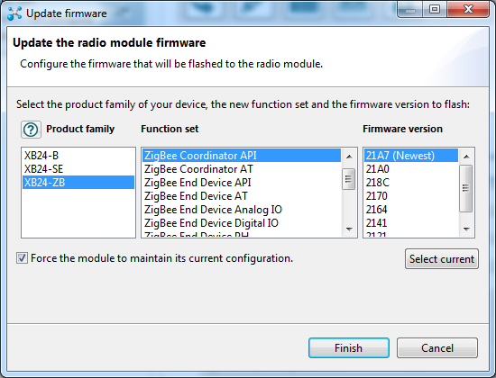
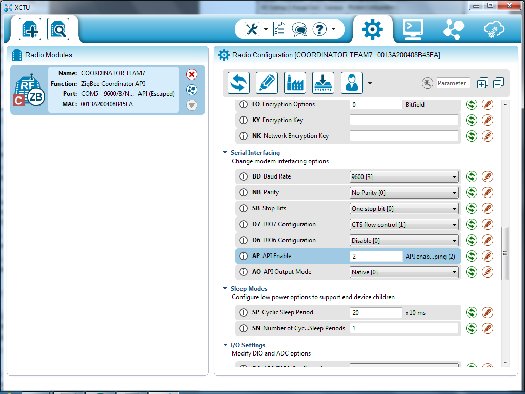
- 1x XBee radio configured as ZigBee Coordinator API.
- 1x XBee radio configured as ZigBee Router API.
- 2x USB cable for the XBee.
- 2x XBee Explorer.
- 1x Breakout board.
- 1x Motor.
- 1x Temperature Sensor (LM35).
- 1x Transistor.
- 1x LDR (Light Dependent Resistor).
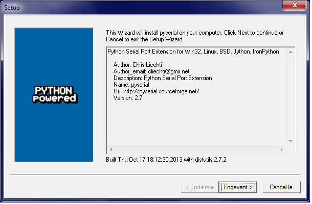
Moreover, again we leave here some of the software you will need (the same as in the previous practice).
- XCTU.
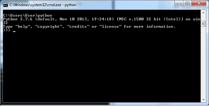
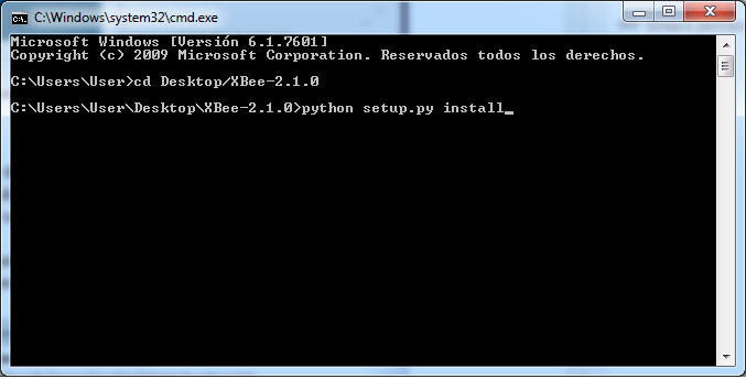
- Python 2.7.
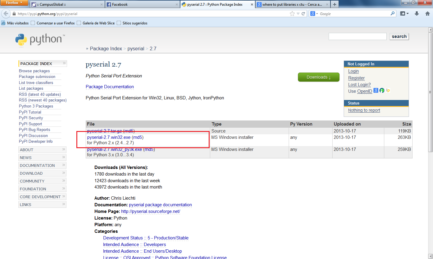
- XBee library for Python.
- Pyserial library for Python (mirror).
- XBee library for Arduino.
The installation is explained in the previous practice too, review it if you have not seen it yet.
Part 1 - Warm Up
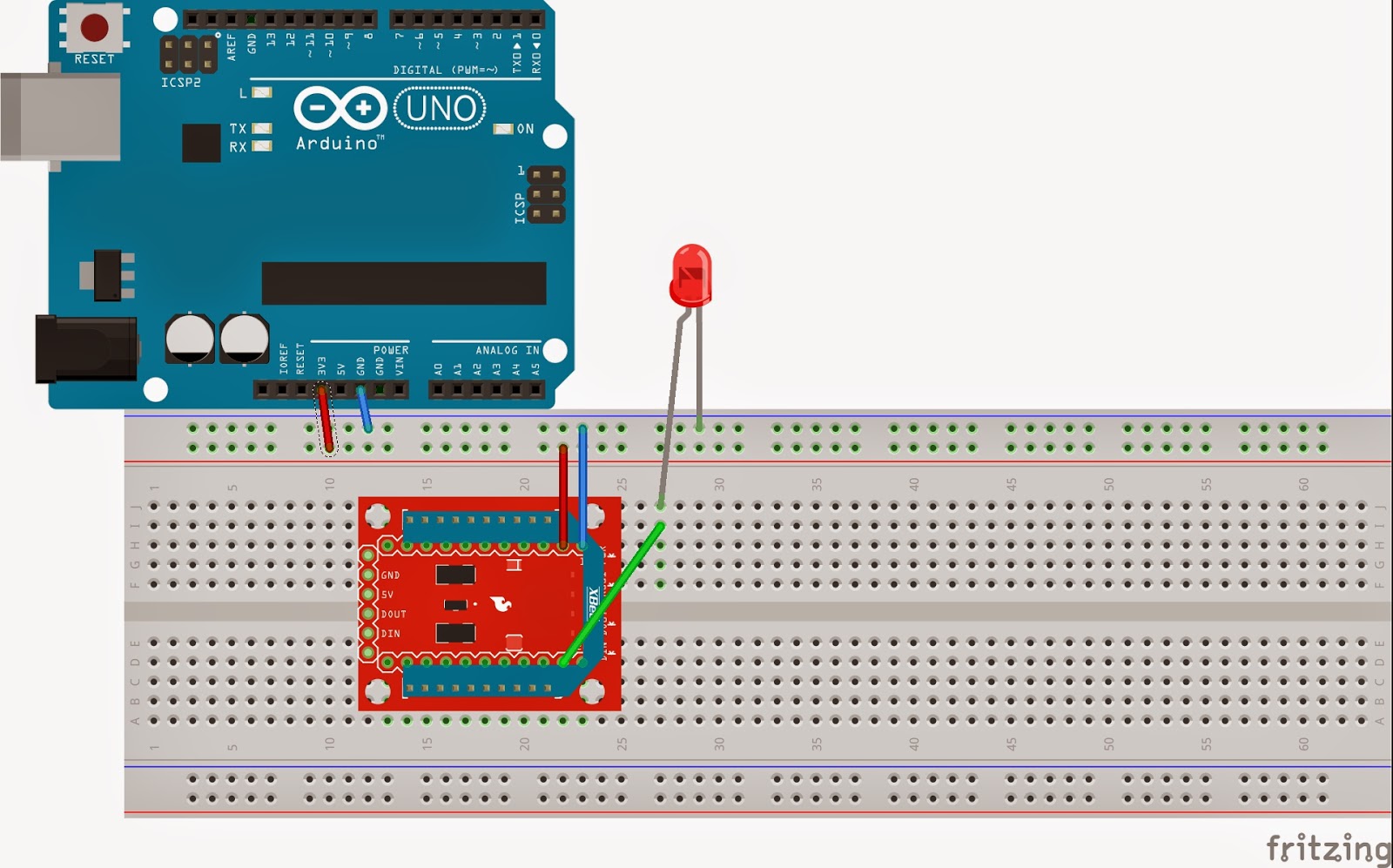
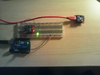
As a warm up we did the activity explained in the course guide [1]. It consists in a circuit formed by an LDR, whose analogic values are sent to an XBee through one of its pins; this information is received at another XBee which is plugged to a computer. This computer executes a Python program which reads the messages when received and shows them through the screen. Note that any Arduino is being used here.
 |
| Figure 1: Setup of the XBee that sends LDR state to the computer connected XBee |
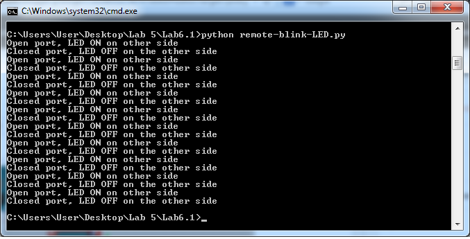
In the following screenshots you can see the messages that are sent. You can see that two of them in a red rectangle: the first one represents a measure with the room plenty of light, and the second one without light.
 |
| Figure 2: Receiving values from XBee |
This task can be done in two different ways: sinchronously and asinchronously. The code is attached below.
Synchronous code
1 2 3 4 5 6 7 8 9 10 11 12 13 14 15 16 | import serial from xbee import ZigBee print 'Printing data from remote XBee' serial_port = serial.Serial('COM4', 9600) zigbee = ZigBee(serial_port, escape=True) while True: try: print zigbee.wait_read_frame() except KeyboardInterrupt: break zigbee.halt() serial_port.close() |
Asynchronous code
1 2 3 4 5 6 7 8 9 10 11 12 13 14 15 16 17 18 19 20 21 22 23 24 25 | import serial import time from xbee import ZigBee print 'Asynchronously printing data from remote XBee' serial_port = serial.Serial('/dev/ttyUSB0', 9600) def print_data(data): """ This method is called whenever data is received. Its only argument is the data within the frame. """ print data['samples'] zigbee = ZigBee(serial_port, escaped=True, callback = print_data) while True: try: time.sleep(0.001) except KeyboardInterrupt: break zigbee.halt() serial_port.close() |
Part 2 - Activating a Fan
On this extra project part, we are going to design a system that will allow us to refrigerate a server's room (e.g. a CDN). The heat production produced by the servers on data center is one of the main problems that administrators have to face. The heat excess in servers room negatively impacts the equipment performance and shortens their useful life. Also, if we are dealing with critical systems like nuclear centers, having a real-time control on the temperature is a priority. So, let us try to develop a system that automatically refrigerates the servers when needed, making the administrators could invest their time in other useful tasks.
On the room's side we need:
- 1x Temperature Sensor.
- 1x Fan (motor).
- 1x Xbee.
- 1x Arduino Uno.
- A way to feed the Arduino (a normal PC will be enough).
On the control center we will need:
- 1x Xbee
- 1x PC running python code
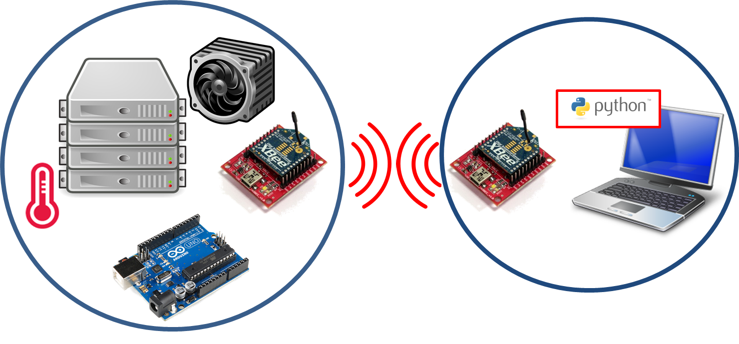 |
| Figure 3: System overview |
As shown above, the two main parts of the whole system communicate each other by using a pair of Xbee modules. On the server side, the Xbee will send the data captured by the temperature sensor. The Xbee situated on the control center side will get this data and forward it to the PC, which runs a python code that is able to decode the received data and compare it with a predefined temperature threshold. When the threshold is overcome, the code will generate an alert packet advising the Arduino on the servers side to activate the ventilator (motor). This packet, naturally, will be forwarded from the control center Xbee to the server side Xbee.
It is important to note that, because of collisions high probability, the Xbee on the servers side will transmit the temperature data periodically. That is, sending a temperature data packet, waiting for possible motor activation packet, and then, if no packet is received, sending the next captured temperature.
Respect to the code, we have to take into account that the LM35 temperature sensor does not provide the temperature directly. We have found in [2] that a formula has to be computed in order to get the temperature depending on the voltage; since our voltage is 3.3 V, the formula we get is: 3.3 * 100 * readValue / 1024. However, in the code there is this option and another one that we have manually computed by knowing the real temperature of the room in which we were doing the lab: readValue * 18.0 / 212.0.
Respect to the code, we have to take into account that the LM35 temperature sensor does not provide the temperature directly. We have found in [2] that a formula has to be computed in order to get the temperature depending on the voltage; since our voltage is 3.3 V, the formula we get is: 3.3 * 100 * readValue / 1024. However, in the code there is this option and another one that we have manually computed by knowing the real temperature of the room in which we were doing the lab: readValue * 18.0 / 212.0.
Phographs
 |
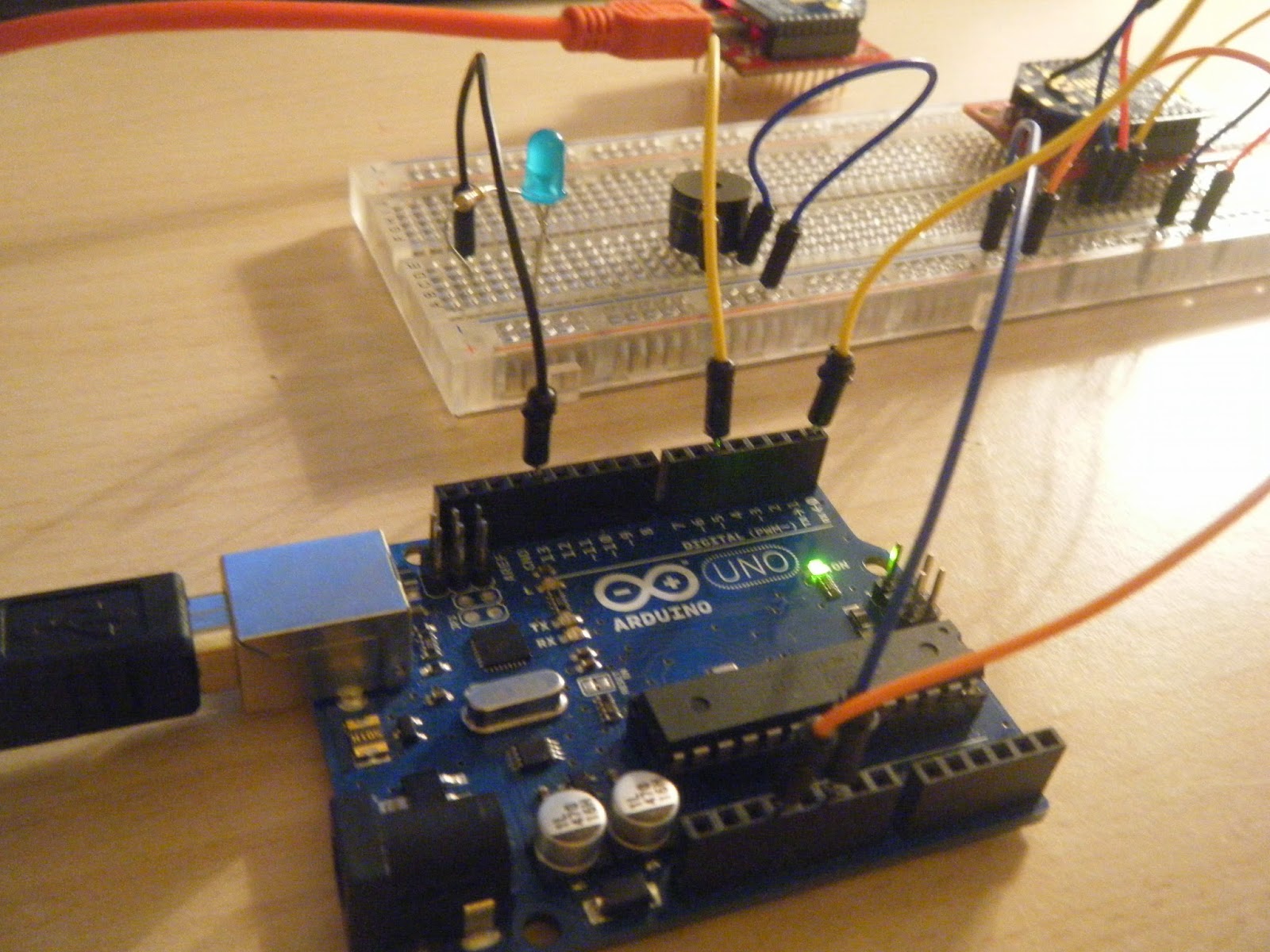
| Figure 4: Photograph of the whole system |
 |
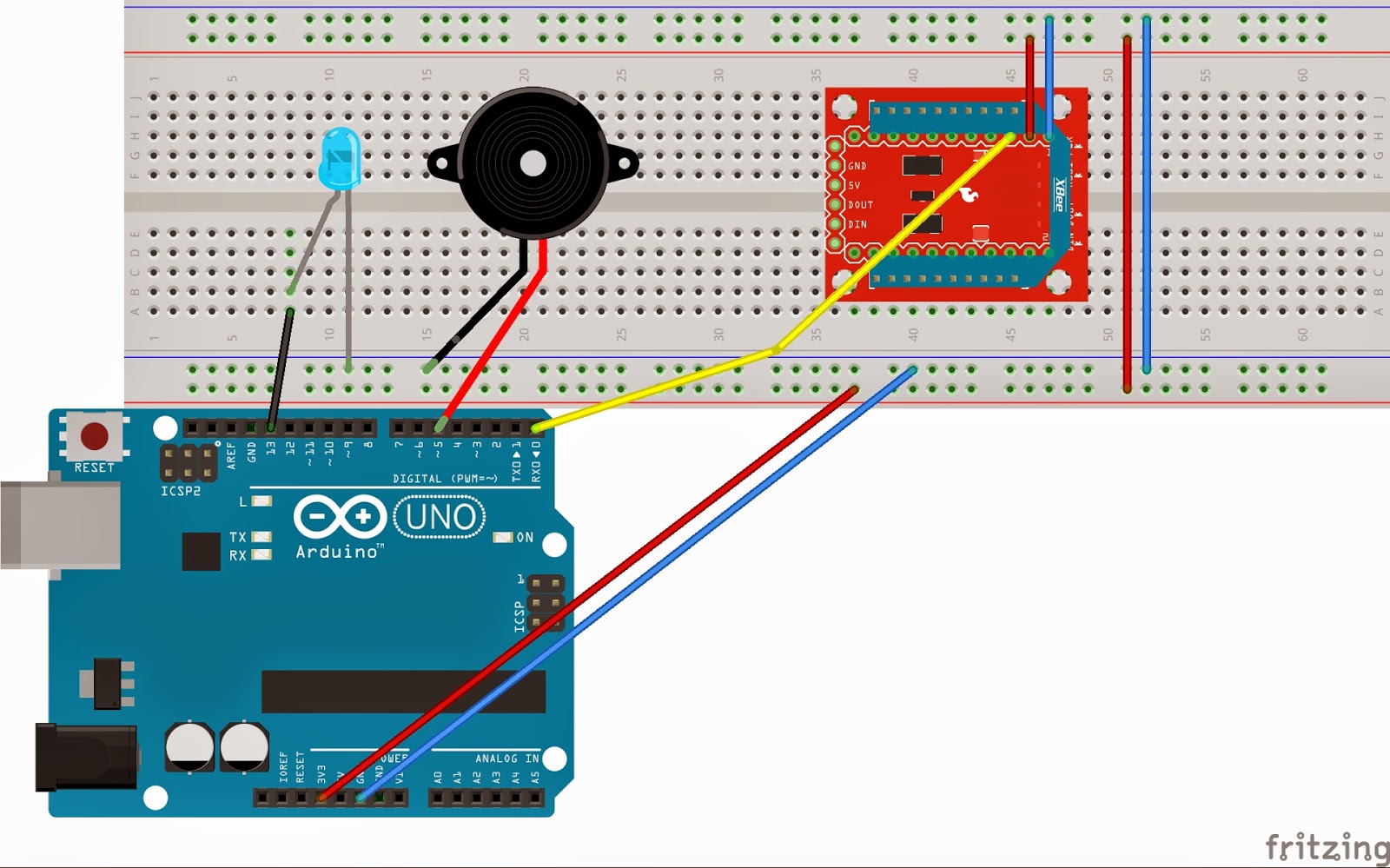
| Figure 5: Photograph of the sensor (temperature) and actuator (motor) system |
Final setup image
 |
| Figure 6: Final setup of the temperature based fan |
Video
Arduino Code
1 2 3 4 5 6 7 8 9 10 11 12 13 14 15 16 17 18 19 20 21 22 23 24 25 26 27 28 29 | // named constants for the switch and motor pins const int STATE_PIN = 2; // the number of the State pin const int FAN_PIN = 5; // the number of the motor pin int DETstate = 0; // variable for reading the state detector status void setup() { // initialize the motor pin as an output: pinMode(FAN_PIN, OUTPUT); digitalWrite(FAN_PIN, LOW); // initialize the switch pin as an input: pinMode(DETstate, INPUT); Serial.begin(9600); } void loop(){ // read the state of the Threshold value: DETstate = digitalRead(STATE_PIN); // check if the activationg motor order is rx if (DETstate == HIGH) { // turn fan on: digitalWrite(FAN_PIN, HIGH); } else { // turn fan off: digitalWrite(FAN_PIN, LOW); } delay(10); } |
Python Code (XBee connected to computer)
1 2 3 4 5 6 7 8 9 10 11 12 13 14 15 16 17 18 19 20 21 22 23 24 25 26 27 28 29 30 31 32 33 34 35 36 37 38 39 40 41 42 43 44 45 46 47 48 49 50 51 52 53 54 55 56 57 58 59 60 61 62 | import serial from xbee import ZigBee def getTemperatureFromData(data): temperature = data['samples'][0]['adc-0'] # temperature = temperature*18.0/212.0 temperature = 3.3 * temperature * 100.0 / 1024.0 return temperature def turnFanOn(xbee): print 'Threshold exceeded! Activating Fans' xbee.send('remote_at', frame_id='A', dest_addr_long='\x00\x13\xA2\x00\x40\x8B\x96\x2E', dest_addr='\xFF\xFE', options='\x02', command='D1', parameter='\x05') def turnFanOff(xbee): xbee.send('remote_at', frame_id='A', dest_addr_long='\x00\x13\xA2\x00\x40\x8B\x96\x2E', dest_addr='\xFF\xFE', options='\x02', command='D1', parameter='\x04') def main(): print 'Receiving temperature values...' serialPort = serial.Serial('COM4', 9600) xbee = ZigBee(serialPort, escaped=True) while True: try: data = xbee.wait_read_frame() if data.keys().count('samples') != 0: temperature = getTemperatureFromData(data) print temperature if (temperature > 21.0): turnFanOn(xbee) else: turnFanOff(xbee) except KeyboardInterrupt: xbee.send('remote_at', frame_id='A', dest_addr_long='\x00\x13\xA2\x00\x40\x8B\x96\x2E', dest_addr='\xFF\xFE', options='\x02', command='D1', parameter='\x04') break xbee.halt() serialPort.close() if __name__ == '__main__': main() else: pass |
References
[1] Course guide: http://www.handsonwsn.org/guide.pdf
[2] LM35 Higher Resolution: http://playground.arduino.cc/Main/LM35HigherResolution
[3] Pictures:[2] LM35 Higher Resolution: http://playground.arduino.cc/Main/LM35HigherResolution
- Server rag: http://tallerpractico.com/wp-content/uploads/2014/02/server_multiple.png
- Temperature sensor: http://www.senseaware.com/wp-content/themes/senseaware/images/img-icon2-large.gif
- Fan: https://cdn1.iconfinder.com/data/icons/STROKE/computer_gadgets/png/400/cpu_fan.png
- PC: http://iconizer.net/files/Vista_Style_Hardware_&_Devices/orig/PortableComputer.png
- Xbee: http://www.robosoftsystems.co.in/roboshop/media/catalog/product/cache/1/image/500x500/9df78eab33525d08d6e5fb8d27136e95/x/b/xbeeadaptor2.jpg
- Python logo: https://www.python.org/static/community_logos/python-logo-master-v3-TM.png
- Android Uno: http://www.sacosta.org/rfid_castellano/logo_arduino.jpg


