Pages

Wednesday 11 June 2014

Practice - Remotely controlling a car with Arduino by using Xbee

About

In this post we explain the process as usual. However, if you prefer it, you can download our class presentation slides by clicking on the dropbox link below:

Description

This time we are going to show you our final project for the Wireless Sensor Networks course, which consists in a remote controlled car built with an Arduino.

Communication between the remote control and the car is going to be supported with XBee's. As usual, here is the list of the needed material to the final build:
  • Hookup wires
  • 1x Arduino Uno
  • 2x XBee (with XBee explorer)
  • 2x BC547 Transistor 
  • 2x 1N4007 Diodes
  • 2x 1KOhm Resistors
  • 3x 10KOhm Resistors
  • 3x Push Buttons
  • 6x 1,5V Batteries (2x AAA + 4 x AA)
  • 2x  Battery Holders (one with capcacity 2 and the other with cap. 4)
  • 2x Motors
  • 3x Wheels  (one for support)
  • ... 
Before showing the circuit and the code used, we want to explain you some features about the electronics that we have applied on the design, which will roughly give you the needed knowledge:

Voltage batteries

When using circuits with different voltages, you have to connect their grounds together to provide a common ground. In our case, we have used 3V(2x 1,5V) and 6V (4x 1,5V) batteries for feeding one XBee and the motors, respectively.

Transistor

A transistor is an electronic device that can be used on circuits for amplifying or switching purposes. The transistor that we have used (of type Negative-Positive-Negative, NPN) is bipolar junction type and has three terminals (base, collector and emitter), which currents and voltages depend on the others, i.e. current on the base terminal controls the current on collector and emitter.

In our case, we have used transistors as switches, changing their state from OFF to ON as desired, in order to have control on the power supply. This can be done because transistors do not let the current path unless a saturation voltage on the Collector pin is reached.

Figure : NPN Transistor Scheme [1]
When maximum Collector current flows the transistor is said to be Saturated. The value of the Base resistor determines how much input voltage is required and corresponding Base current to switch the transistor fully “ON”. In our case, we had to implement a voltage divisor in order to get an input base intensity low enough to make the transistor act as a digital switch.

Figure : BC547 Transistor [2]

Diode

Diode is a polarized component which can go only one way in the circuit (it let the current path just in one direction) and it has a stripe on one end. That end is the negative end, or cathode, of the diode. The other end is the positive end, or anode. The anode of the diode is connected to the ground of the motor and the cathode of the diode to the power of the motor.

This may seem backward, and in fact, it is. The diode will help prevent any back-voltage generated by the motor from going back into the circuit. Back voltage will flow in the opposite direction of the voltage supply (must be avoided). The diodes we have used are Diodes 1N4007.

Figure: Diode 1N4007

Assembly of the pieces

To mount the car we used the breadboard as the support of all the materials (e.g. XBee Explorer, hookup wires, batteries, motors). We needed some way to stick all these materials; therefore we used some adhesive tape along with mini-boards of cork so that motors and batteries could be well fixed to the breadboard.

Figure: Car ready to be build (left circuit is the controller)
Figure: Put the motors over the first cork layer and stick them with adhesive tape (I)
Figure: Put the motors over the first cork layer and stick them with adhesive tape (II)

Figure: Cork layer used to mount the car
Figure: Stick the batteries to the last cork layer (there are 3 layers)

Figure: Final circuit (without battery feeding the XBee)

Figure: Final circuit (with battery feeding the XBee)
Moreover, we had problems with motors and wheels since the axis of the motors was not wide enough to be put in the wheel. To solve this we used some elastic weave put along the motor axis and then we put some adhesive tape over it. This made enough space for the wheel to fit well in the axis. Another possibility, which could work better, consists in adding blu-tack in the joint between the wheel and the axis. In any case, try to get a wheel that fits perfectly the motor axis to avoid these shoddy works.

Figure: Motor axis covered by elastic weave to fit into the wheel hole

Respect to the motors, it was necessary to weld them to hookup wires since it was not done. The motors we used are the ones at [3].

Figure: Welding the hookup wires to the motor (I)

Figure: Welding the hookup wires to the motor

There is also a support wheel which is not actioned by a motor. We also stuck to the last cork layer using blu-tack. It made that the height of the breadboard increased and it made not work completely well; ideally, it would have been put such that the height of the breadboard was completely straight.

Figure: Support wheel stuck with blu-tack

Finally, after adding all these components we have the final result:

Figure: Final car with the remote control to drive it

Circuits

Figure: Controller circuit
Figure: Car circuit


Code


  1
  2
  3
  4
  5
  6
  7
  8
  9
 10
 11
 12
 13
 14
 15
 16
 17
 18
 19
 20
 21
 22
 23
 24
 25
 26
 27
 28
 29
 30
 31
 32
 33
 34
 35
 36
 37
 38
 39
 40
 41
 42
 43
 44
 45
 46
 47
 48
 49
 50
 51
 52
 53
 54
 55
 56
 57
 58
 59
 60
 61
 62
 63
 64
 65
 66
 67
 68
 69
 70
 71
 72
 73
 74
 75
 76
 77
 78
 79
 80
 81
 82
 83
 84
 85
 86
 87
 88
 89
 90
 91
 92
 93
 94
 95
 96
 97
 98
 99
100
101
102
103
104
105
106
107
108
109
110
111
112
113
114
115
116
117
118
119
120
121
122
123
124
125
126
127
128
129
130
131
132
133
134
135
136
137
138
139
140
141
142
143
144
145
146
147
148
149
150
151
152
153
/**
 * This code is used to control the remote car by sending
 * messages through an XBee.
 */

// Pins of the Arduino to which the switches to move the car are connected
const int LEFT_PIN = 2;
const int FORW_PIN = 3;
const int RIGHT_PIN = 4;

// Pins to which we will transmit the information we want to send to the XBee
const int D1_PIN = 8; // corresponds to right wheel
const int D2_PIN = 9; // corresponds to left wheel

// Keeps track of the desired remote on/off state (left, right, forward)
int lRI = false; 
int rRI = false;
int fRI = false;

// Keeps track of the previous remote on/off state
int last_lRI= false;
int last_rRI = false;
int last_fRI = false;

// records last time the remote was re-set to keep it in sync
unsigned long lastSent = 0;

void setup()
{  
  // declare the switch (directions) pins as inputs   
  pinMode(LEFT_PIN, INPUT);
  pinMode(FORW_PIN, INPUT);
  pinMode(RIGHT_PIN, INPUT);
  Serial.begin(9600);
}

void loop()
{
  setRemoteIndicators();
  sendInformation();
}

// Read the value of the switches
//   digitalRead() checks to see if there is voltage on the pin or not  
void setRemoteIndicators()
{
  if (digitalRead(LEFT_PIN) == HIGH) // move left
  {
    lRI = true;
    rRI = false;
    fRI = false;
  } 
  else if (digitalRead(FORW_PIN) == HIGH) // move forward
  {
    lRI = false;
    rRI = false;
    fRI = true;
  }
  else if (digitalRead(RIGHT_PIN) == HIGH) // move right
  {
    lRI = false;
    rRI = true;
    fRI = false;
  }
  else // do not move
  {
    lRI = false;
    rRI = false;
    fRI = false;
  }
}

void sendInformation()
{
  // set the indicators immediately when there's a state change
  if (lRI != last_lRI)
  {
    if (!lRI) setRemoteState(0x4,'1');
    if (lRI) setRemoteState(0x5,'1');
    last_lRI = lRI;
  }
  delay(10);
  
  if (rRI != last_rRI)
  {
    if (!rRI) setRemoteState(0x4,'2');
    if (rRI) setRemoteState(0x5,'2');
    last_rRI = rRI;
  }
  delay(10);
  
  if (fRI != last_fRI)
  {
    if (!fRI)
    {
      setRemoteState(0x4,'1');
      setRemoteState(0x4,'2');
    }
    if (fRI)
    {
      setRemoteState(0x5,'1');
      setRemoteState(0x5,'2');
    }
    last_fRI = fRI;
  }

  // re-set the indicator occasionally in case it's out of sync
  if (millis() - lastSent > 10000 )
  {
    if (!lRI) setRemoteState(0x4,'1');
    if (lRI) setRemoteState(0x5,'1');
    delay(10);
    
    if (!rRI) setRemoteState(0x4,'2');
    if (rRI) setRemoteState(0x5,'2');
    lastSent = millis();
  }
}

// Send msg through the xbee (note that the frame has to be formed)
void setRemoteState(int value, char pinNum)
{
  Serial.write(0x7e);//Start byte
  Serial.write((byte)0x0);//Length
  Serial.write(0x10);//Length High
  Serial.write(0x17);//AT Command Request
  Serial.write((byte)0x0);//Frame ID
  Serial.write((byte)0x0);//Serial Number of Destination
  Serial.write((byte)0x0);
  Serial.write((byte)0x0);
  Serial.write((byte)0x0);
  Serial.write((byte)0x0);
  Serial.write((byte)0x0);
  Serial.write(0xFF);
  Serial.write(0xFF);//End of Serial Number of Destinition

  // 16 bit of recipient or 0xFFFE if unknown
  Serial.write(0xFF);
  Serial.write(0xFE);
  Serial.write(0x02);//Apply changes immediately

  //Command name in ASCII characters
  Serial.write('D');
  Serial.write(pinNum);

  //command data in as many bytes after length bytes
  Serial.write(value);

  //checksum is all bytes after length bytes
  long sum = 0x17 + 0xFF+ 0xFF + 0xFF + 0xFE + 0x02 + 'D' + pinNum + value;
  Serial.write (0xFF - ( sum & 0xFF) );
  delay(10); // avoiding overwhelming
} 

Video

References

[1] www.electronics-tutorials.ws/transistor/tran_2.html
[2] www.bhashatech.com/transistors/48-npn-bc547.html
[3] http://www.bricogeek.com/shop/motores/220-motor-micro-metal-dc-con-reductora-298-1.html

Tuesday 3 June 2014

Practice - Measuring Light Pollution in Barcelona

Description

This time we are going to measure some values with sensors and send them automatically to a Visualization Platform (xively.com) through automatically generated json code.
The first part consits in a brief explanation about how to configure the system and how to send our first measurements.
Finally, we are going to extend all this with the aim to provide real evidences of how light pollution affects us and our environment (animals, plants...). As usual, we now provide a list of the material need for this practice, including HW and SW.

The materials we will need are the following:
  • Hookup wires
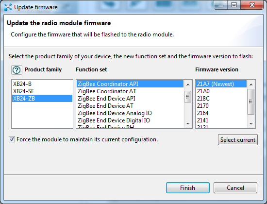
  • 2x XBee (1 configured as ZigBee Router API, 1 configured as ZigBee Coordinator API)
  • 2x XBee Explorer
  • 2x resistors of 22 kOhms (one is for backup)
  • 2x LDR
  • 1x Arduino Uno (to feed one of the XBees)
  • 1x Computer

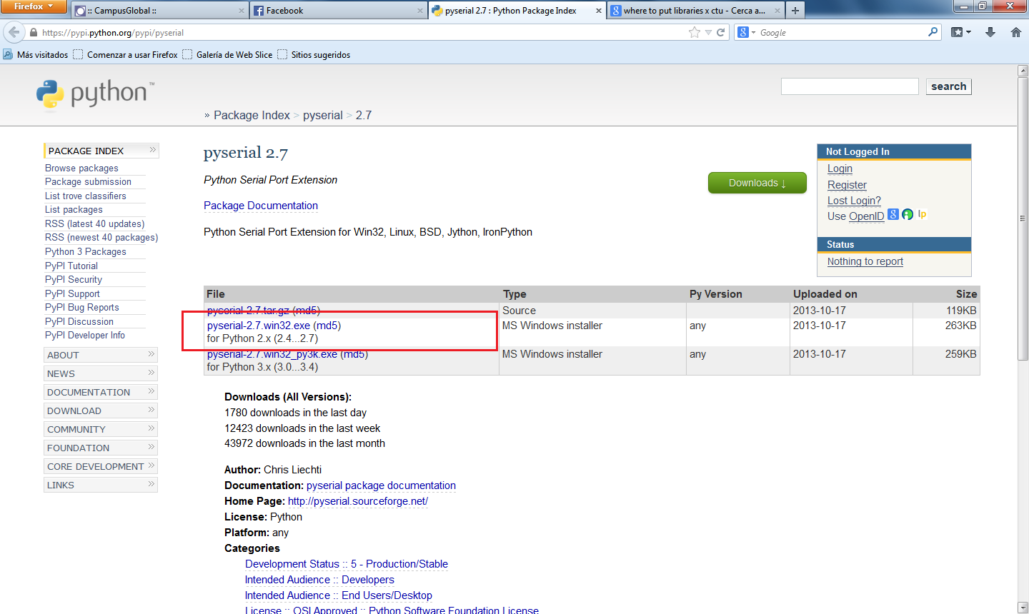
The software you will need is the following:

Part 1

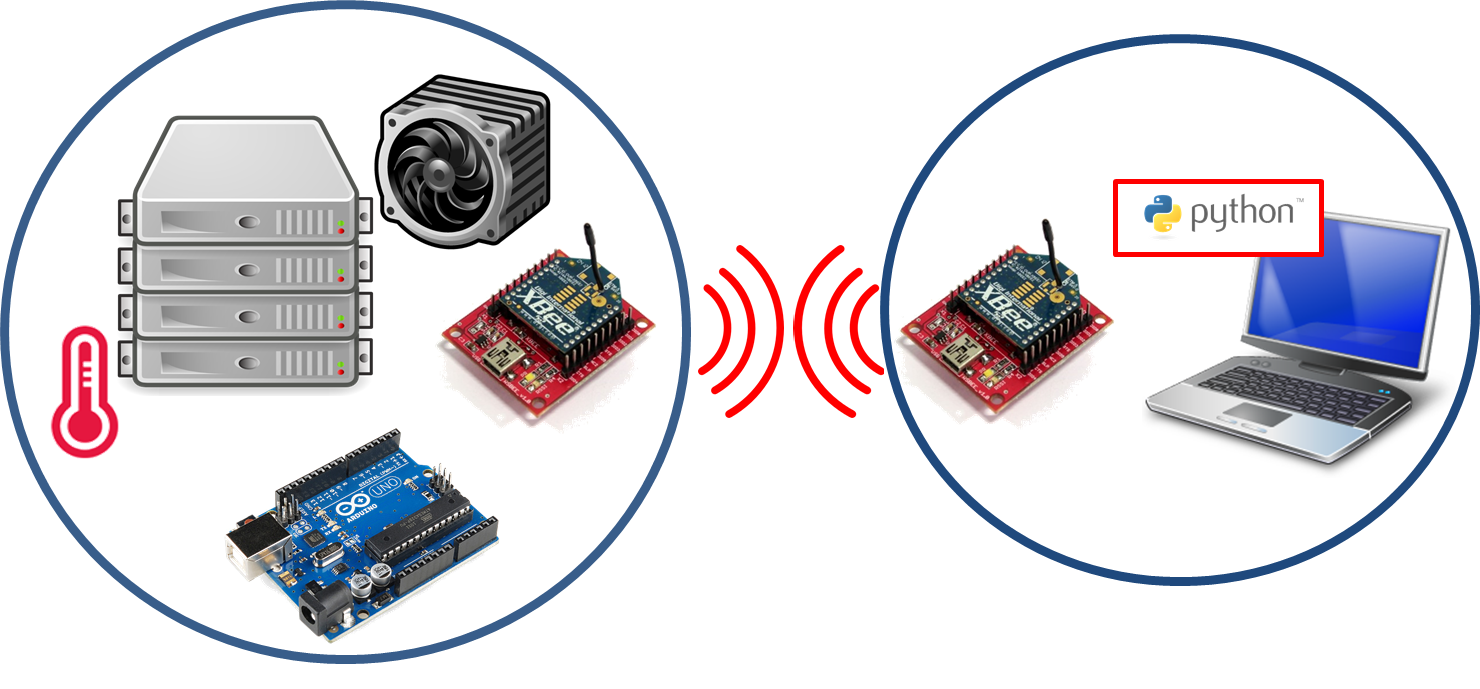
As in previous lab, we have an XBee set to ZigBee Router API and the other XBee set to ZigBee Coordinator API.

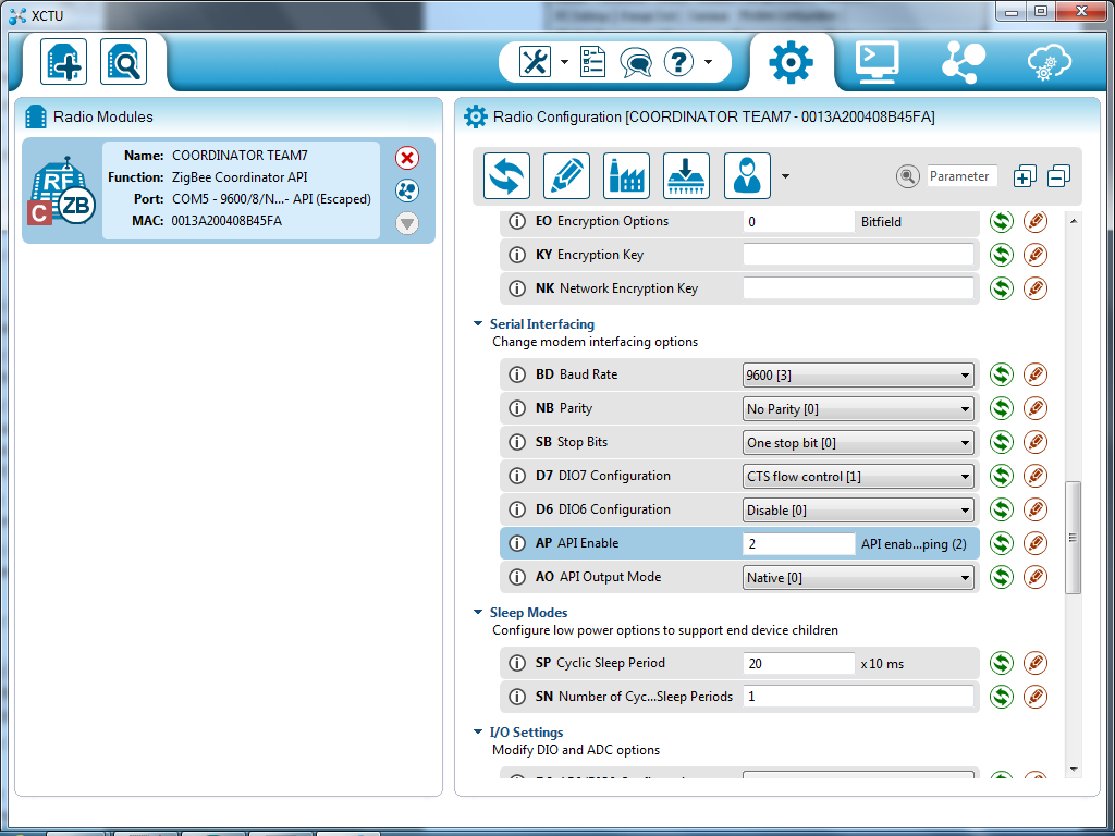
The router has to contain same PAN ID as coordinator and its address in the destination field. The field AP must be set to 2 (API enable) and we also have to configure port DO into ADC in order to receive data from the sensor.

Note that we are setting the IO Sampling Rate with 400 ms, which means that we send packets with rate 2.5 packets/second. We did that in order not to collapse Xively when we upload data.

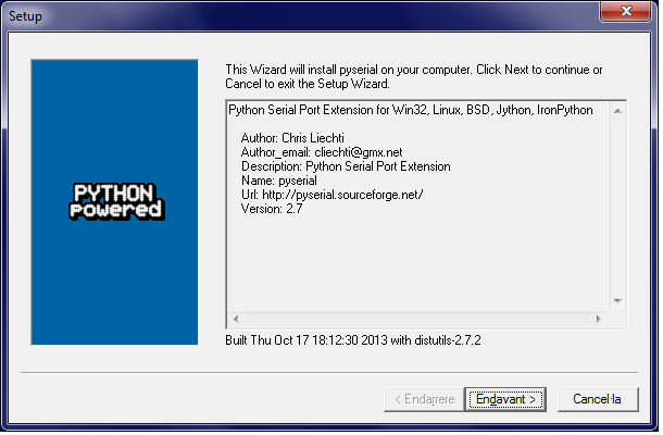
Before sending data to Xively we must ensure that we have available "curl" command to allow communication with the Internet. If you are on windows you should download an executable and add it to your path (if you are working with cmd). You can access your computer's path variable by accessing environment variables on properties menu.

Another issue you must take into account before executing the code is to set the API endpoint with "https" or "http". It is possible that you find troubles with certifieds using "https", so we recomend you to use "http".

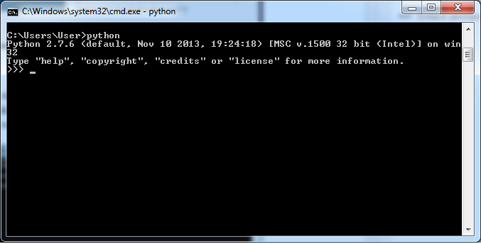
Now we are able to execute the code! If did not have already created an account on Xivel, you can access their webpage and create one. You will also need to add a new device and provide a description of it in order to obtain the "API Endpoint" and the "API Key", which must be included in your python code.

As the image below shows, we have uploaded our measurements into the Xively platform:

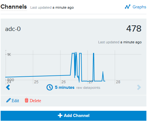
Figure 1: Measurements on Xively
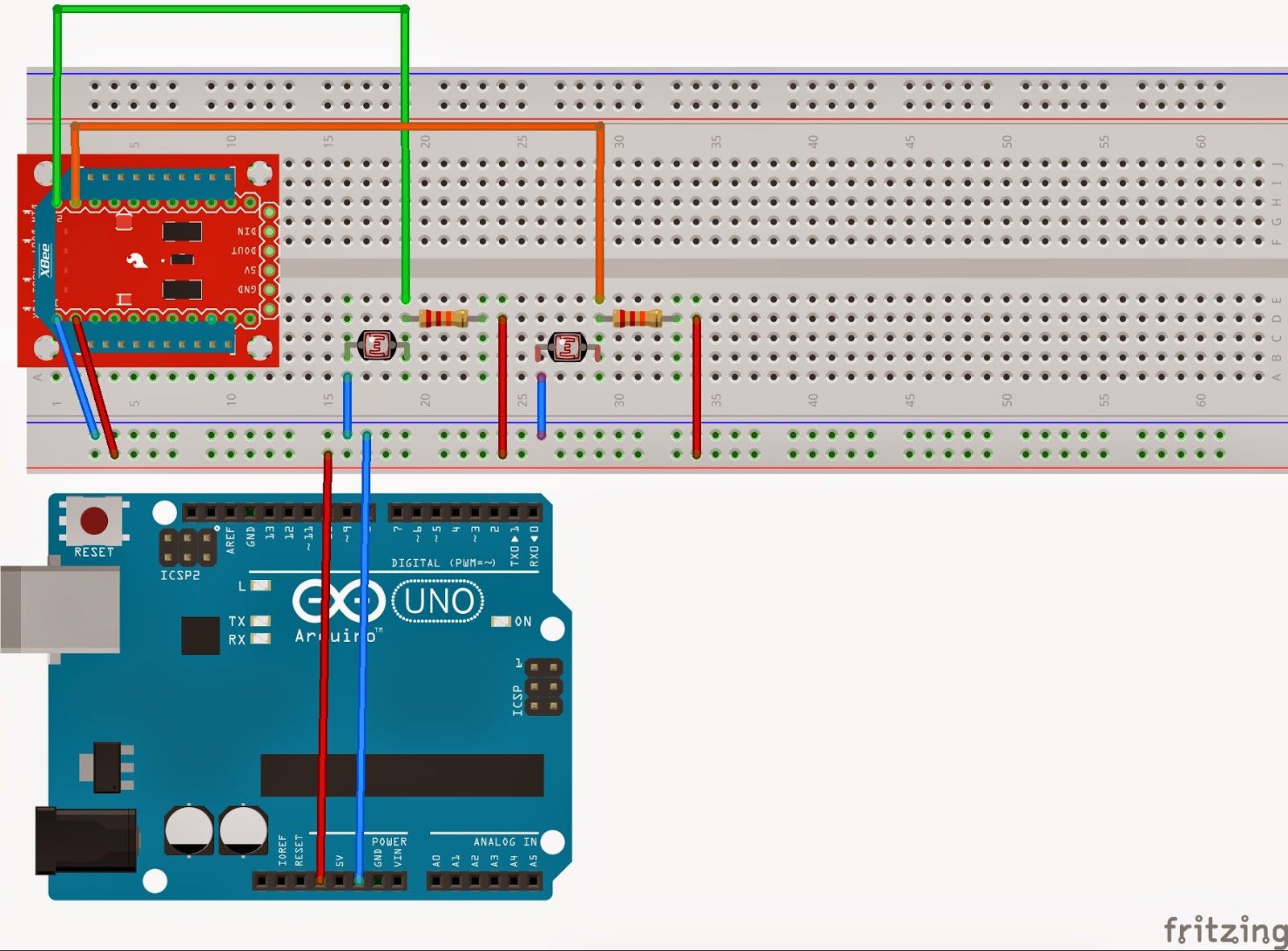
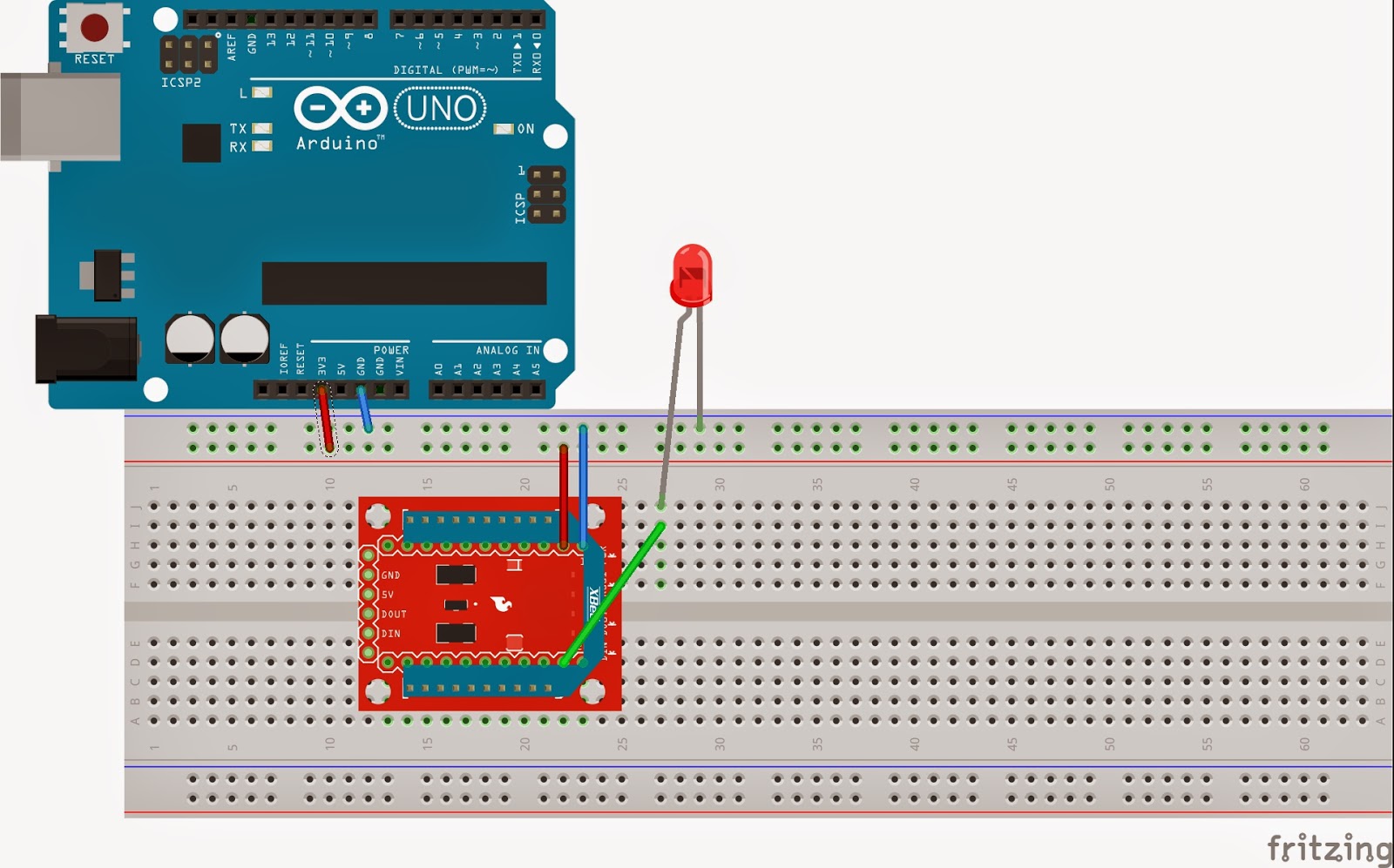
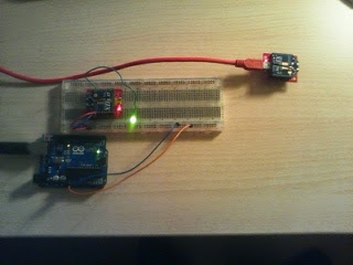
Circuit Part 1

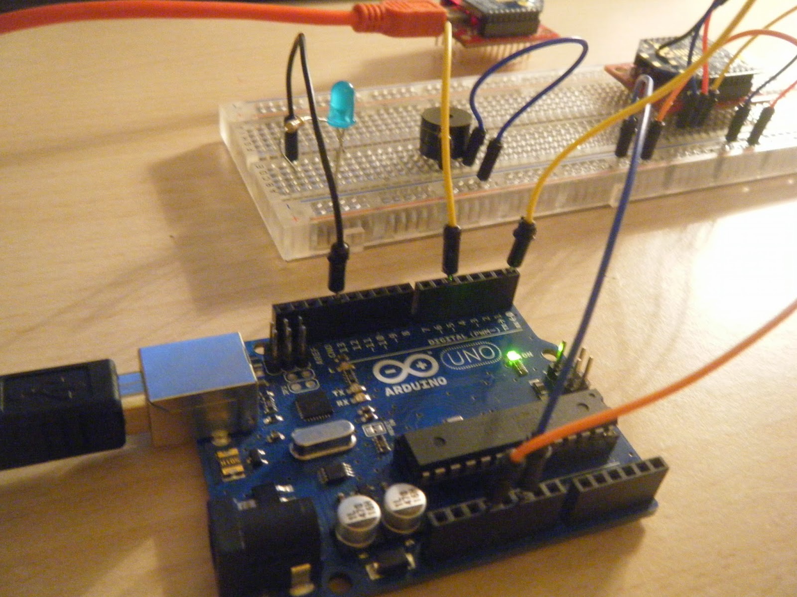
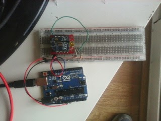
Figure 2: Picture Circuit Part 1
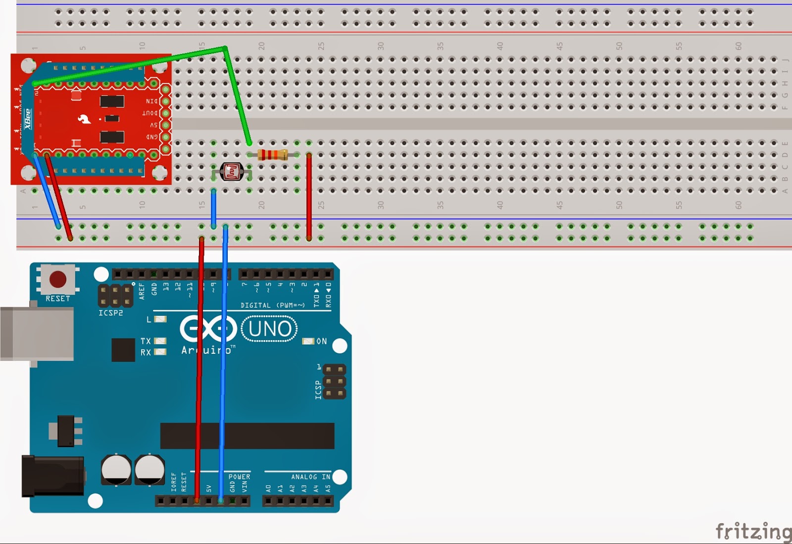
Figure 3: Circuit Part 1

Code Part 1 [3]

The following code reads incoming values of light measurements done on the coordinator side, creates a JSON file and executes the command for uploading this file to Xively platform. A new JSON file is  done and upload every time we receive data.

# Derived from code by Alejandro Andreu
import commands
import json
import serial
import time
import os
from serial import SerialException
from xbee import ZigBee

print 'Asynchronously printing data from remote XBee'

serial_port = serial.Serial('COM5', 9600)

def print_data(data):
    """
    This method is called whenever data is received.
    Its only argument is the data within the frame.
    """
    print data['samples'][0].keys()[0]

    # Create a JSON file and fill it with the received samples
    json_data = {}
    json_data['version'] = '0.2'
    json_data['datastreams'] = ()
    json_data['datastreams'] = json_data['datastreams'] + ({'id': data['samples'][0].keys()[0], 'current_value': str(data['samples'][0].values()[0])},)
    # Add more datastreams if needed
    with open('Xbee2Xively.json', mode='w') as f:
        json.dump(json_data, f, indent = 4)
    # Upload information to Xively. Use your own Api Key and feed identifier
    os.popen('curl --request PUT --data-binary @Xbee2Xively.json --header "X-ApiKey:g14aNzsNGLD0UOvi4wFXpTjzqfliK0JcfgpU0GnubyGUBzKi" --verbose https://api.xively.com/v2/feeds/779242912')

zigbee = ZigBee(serial_port, escaped = True, callback = print_data)

time.sleep(200)

zigbee.halt();
serial_port.close()

Part 2

Introduction/About

In this part we are going to experiment how light pollution affects Barcelona. About light pollution, so far, there is little social conscience, even though it generates numerous harmful consequences such as energy waste (and greenhouse gas emissions resulting from their production). This also effects to human and animals health and psychology, and, even some people could find not a priority, it also damages astronomy activity and generates general loss of perception of the Universe [1]. In fact, it has been shown in recent years that prolonged exposure of the trees to artificial light can cause the trees out of control and produce oxygen at night instead of absorbing carbon dioxide (which is one of the main purposes of plant trees in the city). Hence, we would like to contribute a little by making this project and divulge a bit the problematic.

As obvious, we consider that nowadays it is a must to have well illuminated streets at nights, but it should be a must to provide this light in an adequate, accurate and efficient way. As an example,  all sent laterally light, upward or to paces where it is not needed, does not provide security and visibility and is a waste of energy (environment harm) and money (we pay lot of taxes and the contributors have the right to make our politicians to invest where necessary).

Therefore, we can get some experimental data and go to city hall and force them to:
  • Install streets bulbs horizontally. Use shielded lamps and luminous flux directed only downward.
  • Install preferably sodium vapor lamps of low pressure and adequate power to use.
  • Turn off Monumental and advertising lighting after midnight (there will not be any citizen or tourist contemplating any monument).
  • Prohibit light or laser guns, and any projector that directs light toward the sky.
  • Use asymmetrical floodlights without inclination.
  • Reduce consumption in peak hours, at dawn, by brownout on the public or the selective off lights.


In short, the only way to control light pollution is to reduce the amount of light sent to heaven and reduce general consumption. We have to respect the night ecosystem.

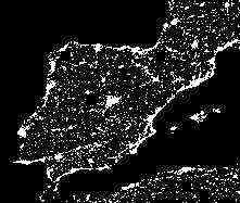
Figure 4: Spanish night map [5]

Getting experimental data

To do this, we are going to use the same procedure as before but we are also adding another sensor for backup. The information of this last sensor would be included on the same json file that we sended before in order to compare the uploaded values on the Xively platform.

The previous IO Sampling Rate was 400 ms, but now we have twice amount of data, so we set this field on 1000 ms, that means 0.5 packet per second (we have 2 sources).

As we do not have enough sensor's precision, we are just going to compare the results obtained of measuring during the day and the night with the theoretical  illuminance values, which are described below:

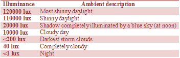
Table 1: Illuminance values [4]
We can see that the equivalence on day-night values must be 120000:1 in the extreme cases. In our case, we obtain measurements on a cloudy day with shadows, so our equivalence should be 500:1.

The following pictures shows the measurements done by both sensors, which are done with the data received from Xively using the following cmd command:

curl --request GET http://api.xively.com/v2/feeds/YOUR_FEED/datastreams/YOUR_CHANNEL.csv?key=YOUR_API_KEY&start=2013-12-22&duration=24hours&interval=900&limit=100&interval_type=discrete" > data.csv

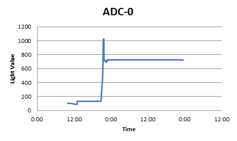
Figure 5: ADC-0 measurements


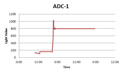
Figure 6: ADC-1 measurements

We can observe that measured light on the night is not far enough from received during a shinny day, so we can observe an equivalence of 4:1, which is so far away of our assumptions.
Note that both graphs show the same data from 23:00 of the first day to 0.00 of the second day. This is because Xively gaves us a graphic with the last token value (at 23:30) extended until the moment we requested the data.
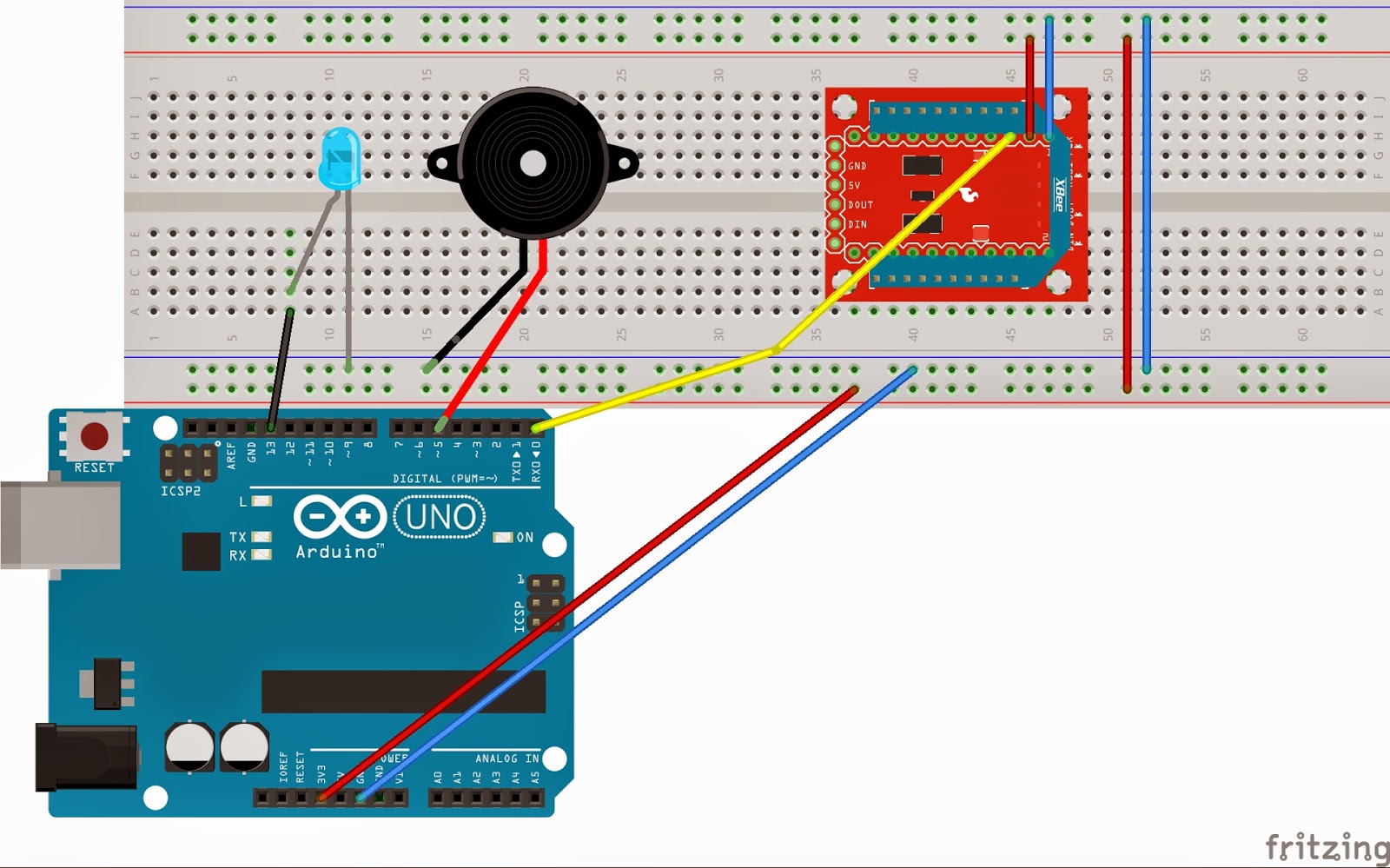
Circuit Part 2

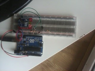
Figure 7: Picture Circuit Part 2
Figure 8: Circuit Part 2

Code Part 2 [3]

# Derived from code by Alejandro Andreu
import commands
import json
import serial
import time
import os
from serial import SerialException
from xbee import ZigBee

print 'Asynchronously printing data from remote XBee'

serial_port = serial.Serial('COM5', 9600)

def print_data(data):
    """
    This method is called whenever data is received.
    Its only argument is the data within the frame.
    """
    print data['samples'][0].keys()[0]
    print data['samples'][0].values()[0]
    print data['samples'][0].keys()[1]
    print data['samples'][0].values()[1]
    
    # Create a JSON file and fill it with the received samples
    json_data = {}
    json_data['version'] = '0.2'
    json_data['datastreams'] = ()
    json_data['datastreams'] = json_data['datastreams'] + ({'id': data['samples'][0].keys()[0], 'current_value': str(data['samples'][0].values()[0])},)
 
    with open('Xbee2Xively.json', mode='w') as f:
        json.dump(json_data, f, indent = 4)
  
 # Add data from adc-1 pin
    json_data1 = {}
    json_data1['version'] = '0.2'
    json_data1['datastreams'] = ()
    json_data1['datastreams'] = json_data['datastreams'] + ({'id': data['samples'][0].keys()[1], 'current_value': str(data['samples'][0].values()[1])},)
 
    with open('Xbee2Xively.json', mode='w') as f:
        json.dump(json_data1, f, indent = 4)
   
 
zigbee = ZigBee(serial_port, callback = print_data)
while True:
    try:
        time.sleep(500)
    except KeyboardInterrupt:
        break

zigbee.halt();
serial_port.close()

References

[1] Python software and libraries, retrieved from: https://www.python.org/
[2] XBee library for Arduino, retrieved from: https://code.google.com/p/xbee-arduino/
[3] Version of the code "upload_to_xively.py" from Jaume Barceló and Luis Sanabria
[4] Light pollution information from "Universidad de Murcia" report, retrieved from:  http://www.um.es/cieloscuro/documentos/divulgacion/cluminica_dos_palabras.pdf
[5] Image from "celfosc", retrieved from: http://www.celfosc.org/
[6] Illuminance information from Wikipedia, retrieved from: http://en.wikipedia.org/wiki/Daylight

Saturday 24 May 2014

Practice - Activating a Fan Depending on the Temperature

Description

In this lab we have been experimenting with the comunication between an XBee connected to a PC and another XBee that is taking signals from a sensor to send them (this signals are caught using the DIO ports of the XBee explorer). The information that comes from the sensors is sent from an XBee to the other; the information received by the second XBee will be read serially with a computer using a Python program, that will process the read (e.g. showing it or generating a response). Both XBees work in API mode as in the last practice (Morse Code).

In the first part we will show the messages sent by an XBee which is connected to a LDR, whereas in the second part a motor will be turned on when the temperature reaches a defined value (e.g. 30ºC).

The material we will need is the following:
  • Hookup wires.
  • 1x Arduino board.
  • 1x USB A-to-B cable for the Arduino.
  • 1x XBee radio configured as ZigBee Coordinator API.
  • 1x XBee radio configured as ZigBee Router API.
  • 2x USB cable for the XBee.
  • 2x XBee Explorer.
  • 1x Breakout board.
  • 1x Motor.
  • 1x Temperature Sensor (LM35).
  • 1x Transistor.
  • 1x LDR (Light Dependent Resistor).
Moreover, again we leave here some of the software you will need (the same as in the previous practice). 
The installation is explained in the previous practice too, review it if you have not seen it yet.

Part 1 - Warm Up

As a warm up we did the activity explained in the course guide [1]. It consists in a circuit formed by an LDR, whose analogic values are sent to an XBee through one of its pins; this information is received at another XBee which is plugged to a computer. This computer executes a Python program which reads the messages when received and shows them through the screen. Note that any Arduino is being used here.

Figure 1: Setup of  the XBee that sends LDR state to the computer connected XBee

In the following screenshots you can see the messages that are sent. You can see that two of them in a red rectangle: the first one represents a measure with the room plenty of light, and the second one without light.

Figure 2: Receiving values from XBee

This task can be done in two different ways: sinchronously and asinchronously. The code is attached below.

Synchronous code

 1
 2
 3
 4
 5
 6
 7
 8
 9
10
11
12
13
14
15
16
import serial
from xbee import ZigBee

print 'Printing data from remote XBee'

serial_port = serial.Serial('COM4', 9600)
zigbee = ZigBee(serial_port, escape=True)

while True:
    try:
        print zigbee.wait_read_frame()
    except KeyboardInterrupt:
        break

zigbee.halt()
serial_port.close()

Asynchronous code


 1
 2
 3
 4
 5
 6
 7
 8
 9
10
11
12
13
14
15
16
17
18
19
20
21
22
23
24
25
import serial
import time
from xbee import ZigBee

print 'Asynchronously printing data from remote XBee'

serial_port = serial.Serial('/dev/ttyUSB0', 9600)

def print_data(data):
    """
    This method is called whenever data is received.
    Its only argument is the data within the frame.
    """
    print data['samples']

zigbee = ZigBee(serial_port, escaped=True, callback = print_data)

while True:
    try:
        time.sleep(0.001)
    except KeyboardInterrupt:
        break

zigbee.halt()
serial_port.close()

Part 2 - Activating a Fan

On this extra project part, we are going to design a system that will allow us to refrigerate a server's room (e.g. a CDN). The heat production produced by the servers on data center is one of the main problems that administrators have to face. The heat excess in servers room negatively impacts the equipment performance and shortens their useful life. Also, if we are dealing with critical systems like nuclear centers, having a real-time control on the temperature is a priority. So, let us try to develop a system that automatically refrigerates the servers when needed, making the administrators could invest their time in other useful tasks.

On the room's side we need:

  • 1x Temperature Sensor.
  • 1x Fan (motor).
  • 1x Xbee.
  • 1x Arduino Uno.
  • A way to feed the Arduino (a normal PC will be enough).

On the control center we will need:

  • 1x Xbee
  • 1x PC running python code

Figure 3: System overview
As shown above, the two main parts of the whole system communicate each other by using a pair of Xbee modules. On the server side, the Xbee will send the data captured by the temperature sensor. The Xbee situated on the control center side will get this data and forward it to the PC, which runs a python code that is able to decode the received data and compare it with a predefined temperature threshold. When the threshold is overcome, the code will generate an alert packet advising the Arduino on the servers side to activate the ventilator (motor). This packet, naturally, will be forwarded from the control center Xbee to the server side Xbee.

It is important to note that, because of collisions high probability, the Xbee on the servers side will transmit the temperature data periodically. That is, sending a temperature data packet, waiting for possible motor activation packet, and then, if no packet is received, sending the next captured temperature.

Respect to the code, we have to take into account that the LM35 temperature sensor does not provide the temperature directly. We have found in [2] that a formula has to be computed in order to get the temperature depending on the voltage; since our voltage is 3.3 V, the formula we get is: 3.3 * 100 * readValue / 1024. However, in the code there is this option and another one that we have manually computed by knowing the real temperature of the room in which we were doing the lab: readValue * 18.0 / 212.0.

Phographs

Figure 4: Photograph of the whole system

Figure 5: Photograph of the sensor (temperature) and actuator (motor) system

Final setup image


Figure 6: Final setup of the temperature based fan

Video


Arduino Code


 1
 2
 3
 4
 5
 6
 7
 8
 9
10
11
12
13
14
15
16
17
18
19
20
21
22
23
24
25
26
27
28
29
// named constants for the switch and motor pins
const int STATE_PIN = 2; // the number of the State pin
const int  FAN_PIN =  5; // the number of the motor pin

int DETstate = 0;  // variable for reading the state detector status

void setup() {
  // initialize the motor pin as an output:
  pinMode(FAN_PIN, OUTPUT);
  digitalWrite(FAN_PIN, LOW); 
  // initialize the switch pin as an input:
  pinMode(DETstate, INPUT);
  Serial.begin(9600); 
}

void loop(){
  // read the state of the Threshold value:
  DETstate = digitalRead(STATE_PIN);
  // check if the activationg motor order is rx
  if (DETstate == HIGH) {     
    // turn fan on:    
    digitalWrite(FAN_PIN, HIGH);  
  } 
  else {
    // turn fan off:
    digitalWrite(FAN_PIN, LOW); 
  }
  delay(10);
}

Python Code (XBee connected to computer)


 1
 2
 3
 4
 5
 6
 7
 8
 9
10
11
12
13
14
15
16
17
18
19
20
21
22
23
24
25
26
27
28
29
30
31
32
33
34
35
36
37
38
39
40
41
42
43
44
45
46
47
48
49
50
51
52
53
54
55
56
57
58
59
60
61
62
import serial
from xbee import ZigBee

def getTemperatureFromData(data):
 temperature = data['samples'][0]['adc-0']
 # temperature = temperature*18.0/212.0
 temperature = 3.3 * temperature * 100.0 / 1024.0
 return temperature

def turnFanOn(xbee):
    print 'Threshold exceeded! Activating Fans'
    xbee.send('remote_at',
                  frame_id='A',
                  dest_addr_long='\x00\x13\xA2\x00\x40\x8B\x96\x2E',
                  dest_addr='\xFF\xFE',
                  options='\x02',
                  command='D1',
                  parameter='\x05')

def turnFanOff(xbee):
    xbee.send('remote_at',
                  frame_id='A',
                  dest_addr_long='\x00\x13\xA2\x00\x40\x8B\x96\x2E',
                  dest_addr='\xFF\xFE',
                  options='\x02',
                  command='D1',
                  parameter='\x04')   
   
def main():
    print 'Receiving temperature values...'
    serialPort = serial.Serial('COM4', 9600)
    xbee = ZigBee(serialPort, escaped=True)
 
    while True:
  try:
   data = xbee.wait_read_frame()
   if data.keys().count('samples') != 0:
    temperature = getTemperatureFromData(data)
    print temperature
    if (temperature > 21.0):
     turnFanOn(xbee)
    else:
     turnFanOff(xbee)
   
  except KeyboardInterrupt:
   xbee.send('remote_at',
       frame_id='A',
       dest_addr_long='\x00\x13\xA2\x00\x40\x8B\x96\x2E',
       dest_addr='\xFF\xFE',
       options='\x02',
       command='D1',
       parameter='\x04')
   break
 
 xbee.halt()
 serialPort.close()
 
if __name__ == '__main__':
 main()
else:
 pass 
  

References

[3] Pictures:

Wednesday 14 May 2014

Practice - Morse Code Player

Description

This time we are going to perform a system that executes specific tasks according to the communication between two XBee. As usual, we are dividing this practicaL exercise into two parts. The first one will show you how to configurate the XBee modules and the Arduino in order to blink a LED at the receiver part. The second part extends that functionality, so we are going to create a Morse code player, which reproduces the characters introduced on the sender side into Morse. To coordinate all this stuff we are going to use Python code with XBee libraries on the sender side.

So, the material that we are going to need is exposed below:
  • Hookup wires.
  • 1 x Arduino board.
  • 1 x USB A-to-B cable for the Arduino.
  • 1 x XBee radio configured as ZigBee Coordinator API.
  • 1 x XBee radio configured as ZigBee Router API.
  • 1 x Breakout board.
  • 1 x USB cable for the XBee.
  • 1 x LED.
  • 1 x Buzzer for output.
The software that you will need to support all this is:
Remember you can find the code used in the code section.

Part 1

The first thing we must do is to install and configure python and the needed libraries for our purpose. After downloading the Python we should see a wizard like the shown on the image below:

Figure 1: Python Wizard

You only have to follow the steps and install it. If you want to execute Python programs with "cmd" tool you should add the directory of the Python to the "path" variable (System > Advanced system settings > Environment variables > System variables > Path ). After doing that you should see the Python version at cmd by typing "python":

Figure 2: Python installation and configuration check

To complete the configuration of the system we must install the XBee and PySerial libraries by the following way:
  • Download the XBee library from the given link (if you have problems with it you can go to the 2nd link and pick the version that suits better to you computer).
Figure 3: XBee library download
  •  Install it by typing "python setup.py install" on the directory where you stored it (C:\Users\User\Destop\XBee-2.1.0 in our case):
Figure 4: XBee library install
  • Download the "pyserial" library and to exactly the same to install it.
Now we have the software properly installed, but the last thing we must do before building the circuit and implementing the code is to set the XBee modules on the API mode. For the coordinator we set it as "ZigBee Coordinator API":

Figure 5: XBee mode
We do the same for the router ("ZigBee Router API"). We also have to enable the API mode at both XBee by setting the "AP" field with number 2.

Figure 6: Enable API mode

The  circuit that we have to build by now is quite simple: a LED connected to the  D1 port of the XBee (note that in this case we only use the arduino to feed the XBee):

Figure 7: Circuit part 1
The code that we must implement on the sender side will send packets to the receiver XBee (we can also send broadcast packets on the same PAN ID with dest_addr_long='\x00\x00\x00\x00\x00\x00\xFF\xFF') that will enable and disable the D1 port in order to let the current path and activate the LED. We also have to take into account in which port we have placed the XBee (COM5 in our case).

To execute it we go to the directory where it is placed and we type "python nameOfTheFile.py"

Figure 8: Code execution

Code Part 1 [3]


 1
 2
 3
 4
 5
 6
 7
 8
 9
10
11
12
13
14
15
16
17
18
19
20
21
22
23
24
25
26
27
28
29
30
31
32
33
34
35
36
37
38
39
40
41
42
43
44
45
#! /usr/bin/python

from xbee import ZigBee
import serial
import time

ser = serial.Serial('COM5', 9600)
xbee = ZigBee(ser, escaped=True)

while True:
    try:
        xbee.send('remote_at',
                  frame_id='A',
                  dest_addr_long='\x00\x13\xA2\x00\x40\x8B\x45\xC8',
                  dest_addr='\xFF\xFE',
                  options='\x02',
                  command='D1',
                  parameter='\x05')
        print("Open port, LED ON on other side")  
        time.sleep(5)
        
        xbee.send('remote_at',
                  frame_id='A',
                  dest_addr_long='\x00\x13\xA2\x00\x40\x8B\x45\xC8',
                  dest_addr='\xFF\xFE',
                  options='\x02',
                  command='D1',
                  parameter='\x04')
        print("Closed port, LED OFF on the other side")
          
        time.sleep(5)
 
  
    except KeyboardInterrupt:
        break

xbee.send('remote_at',
          frame_id='A',
          dest_addr_long='\x00\x00\x00\x00\x00\x00\xFF\xFF',
          dest_addr='\xFF\xFE',
          options='\x02',
          command='D1',
          parameter='\x04')

ser.close()

Images Part 1

Figure 9: Image Circuit Part 1

Part 2

In this second part we are going to change a bit the implementation of the sender side and we are going to add functionalities that the Arduino must implement in order to play the received characters in morse code. The figure below shows the International Morse Code, which we used at the Arduino code for the player:

Figure 10: International Morse Code [4]


We have the same scenario as in part 1, but we have added a LED and a buzzer, which are connected to the Arduino in order to process the information received from the XBee (which receives the characters from the sender XBee).

Figure 11: Circuit part 2
The next step is to implement the "Sender" and the "MorsePlayer" codes and we will see how the LED is turned ON and the buzzers sounds when we receive a character, playing it in morse code. The caracthers are introduced through the keyboard using the Python console.

Images

Figure 12: Circuit part 2 (1)
Figure 13: Cicuit part 2 (2)
Figure 14: Circuit part 2 (3)

Video


Code Part 2: Sender [5]

 1
 2
 3
 4
 5
 6
 7
 8
 9
10
11
12
13
14
15
16
17
18
19
20
21
22
23
24
25
26
27
28
29
30
#! /usr/bin/python

from xbee import ZigBee
from array import *
import serial
import time
from datetime import datetime

ser = serial.Serial('COM4', 9600)
xbee = ZigBee(ser, escaped=True)

while True:
 try:
  input = raw_input('Enter your letter:')
  for c in input:
   tstart = datetime.now()
   xbee.send('tx',
   frame_id='A',
   dest_addr_long='\x00\x13\xA2\x00\x40\x8B\x45\xC8',
   dest_addr='\xFF\xFE',
   data=c)
   response = xbee.wait_read_frame()
   tend = datetime.now()
   print c
   print tend-tstart
   time.sleep(2)
 except KeyboardInterrupt:
  break
  
ser.close()


Code Part 2: Morse Player


  1
  2
  3
  4
  5
  6
  7
  8
  9
 10
 11
 12
 13
 14
 15
 16
 17
 18
 19
 20
 21
 22
 23
 24
 25
 26
 27
 28
 29
 30
 31
 32
 33
 34
 35
 36
 37
 38
 39
 40
 41
 42
 43
 44
 45
 46
 47
 48
 49
 50
 51
 52
 53
 54
 55
 56
 57
 58
 59
 60
 61
 62
 63
 64
 65
 66
 67
 68
 69
 70
 71
 72
 73
 74
 75
 76
 77
 78
 79
 80
 81
 82
 83
 84
 85
 86
 87
 88
 89
 90
 91
 92
 93
 94
 95
 96
 97
 98
 99
100
101
102
103
104
105
106
107
108
109
110
111
112
113
114
115
116
117
118
119
120
121
122
123
124
125
126
127
128
#include <XBee.h>

// Pins
const int ledPin = 13;
const int buzzerPin = 5;

/**
 * Morse Codes
 *  "s" for short (.), "l" for long (-) 
 */
const char longNote = 'l';
const char shortNote = 's';
 
// Morse code for Alphabet
const String letter[26] = {
  "sl","lsss","lsls","lss","s","ssls","lls","ssss","ss","slll","lsl",
  "slss","ll","ls","lll","slls","llsl","sls","sss","l","ssl","sssl","sll","lssl","lsll","llss"}; 

// Morse code for Numbers
const String number[10]= {
  "lllll","sllll","sslll","sssll","ssssl","sssss","lssss","llsss","lllss","lllls"};

/**
 * XBee objects
 */
XBee xbee;
XBeeResponse response;
// create reusable response objects for responses we expect to handle
ZBRxResponse rx;

void setup()
{
  Serial.begin(9600);

  pinMode(ledPin, OUTPUT);
  pinMode(buzzerPin, OUTPUT);

  xbee = XBee();
  response = XBeeResponse();
  rx = ZBRxResponse();

  flashLed(ledPin, 10, 50);
}

void loop()
{
  // 1. This will read any data that is available:
  xbee.readPacket();
  if (xbee.getResponse().isAvailable())
  {
    if (xbee.getResponse().getApiId() == ZB_RX_RESPONSE)
    {
      xbee.getResponse().getZBRxResponse(rx);
      Serial.println(rx.getData(0));
      playCode(rx.getData(0));
    }
  }
}

// Flash the LED for certain number of times and delay between flashes
void flashLed(int pin, int times, int wait)
{
  for (int i = 0; i < times; ++i)
  {
    digitalWrite(pin, HIGH);
    delay(wait);
    digitalWrite(pin, LOW);

    if (i + 1 < times)
    {
      delay(wait);
    }
  }
}

// Play the required tone for the char or int transmitted
void playCode(int ASCII_value)
{
  int intValue = ASCII_value - '0';

  // Integer read
  if (intValue >= 0 && intValue <= 9)
  {
    String toPlay = number[intValue];
    Serial.println(toPlay);
    for (int i = 0; i < toPlay.length(); ++i)
    {
      Serial.println(toPlay[i]);
      if(toPlay.charAt(i) == longNote)    
        largeTone();
      else if(toPlay.charAt(i) == shortNote)
        shortTone();
    } 
  }
  else // Char (A-Z) read
  {
    String toPlay = letter[ASCII_value-65];
    Serial.println(toPlay);
    for (int i = 0; i < toPlay.length(); ++i)
    {
      Serial.println(toPlay[i]);
      if (toPlay.charAt(i) == longNote)    
        largeTone();
      else if (toPlay.charAt(i) == shortNote)
        shortTone();
    }    
  }
}

void largeTone()
{
  delay(50);
  digitalWrite(ledPin, HIGH);
  analogWrite(buzzerPin, 2000);
  delay(500);
  digitalWrite(ledPin, LOW);
  analogWrite(buzzerPin, 0);
}

void shortTone()
{
  delay(50);
  digitalWrite(ledPin, HIGH);
  analogWrite(buzzerPin, 2000);
  delay(100);
  digitalWrite(ledPin, LOW);
  analogWrite(buzzerPin, 0);
}


References

[1] Python software and libraries, retrieved from: https://www.python.org/
[2] XBee library for Arduino, retrieved from: https://code.google.com/p/xbee-arduino/
[3] Code for activate/desactivate D1 port on the receiver side by Jaume Barceló and Luis Sanabria 
[4] International Morse Code, retrieved from: http://en.wikipedia.org/wiki/Morse_code
[5] Version of the code "modified3-blink-LED", by Jaume Barceló and Luis Sanabria